
Intro: Tenant Topology for Cloud Providers running VCF9.1
A five-minute read on what this series is for: helping providers design their backbone and one standard tenant topology on VCF 9.1, the four lab-validated designs that cover every tenant combination, and a target architecture for teams migrating from Cloud Director before they move a single VM.
Intro: Tenant Topology for Cloud Providers running VCF9.1 · 1. Architecture and Foundations · 2. Use-Case A Private-VPC Connectivity to External Networks (Translated) · 3. Use-Case B&C Private-TGW Connectivity to External Networks (Routed or Translated) · 4. Use-Case D One Tenant, Three Exits · 5. Operating the Designs
Every tenant that joins a provider cloud asks the same first question: where does my traffic need to go? The answers come from a short list of exits. Almost every tenant wants the Internet. Most also want a private link back to their own enterprise network over the WAN. Some need the provider's shared services as well, the backup, monitoring or licensing networks a provider runs for all its customers. And a few want all three at once.
The second question follows from the first: what address should my traffic carry when it leaves? Here too there are only a few answers. The enterprise may accept only addresses the provider controls, so the tenant's traffic must be translated on the way out. It may instead want the tenant's real addresses routed through exactly as they are, so its firewalls and logs recognise every workload. Toward the Internet the tenant's private space must simply be hidden. And shared services usually sit in between: open to every tenant, but only through a range the provider hands out.
Put the two questions together and you have the whole catalogue: one, two or three exits, each with one of a few address policies. The combinations are finite, they repeat from customer to customer, and that is what makes them designable.
A provider can build a separate network design for each combination. Or it can decide, once, how its backbone is offered and how every tenant plugs into it. That is what this series is for: it helps a service provider design the two halves that matter, the provider backbone, meaning the gateways, external connections and address blocks the provider owns and exposes, and the tenant topology, meaning the one project, transit gateway and VPC layout every tenant receives. Get those two right and any combination on the list becomes a matter of settings, not of new design.
Standard topology
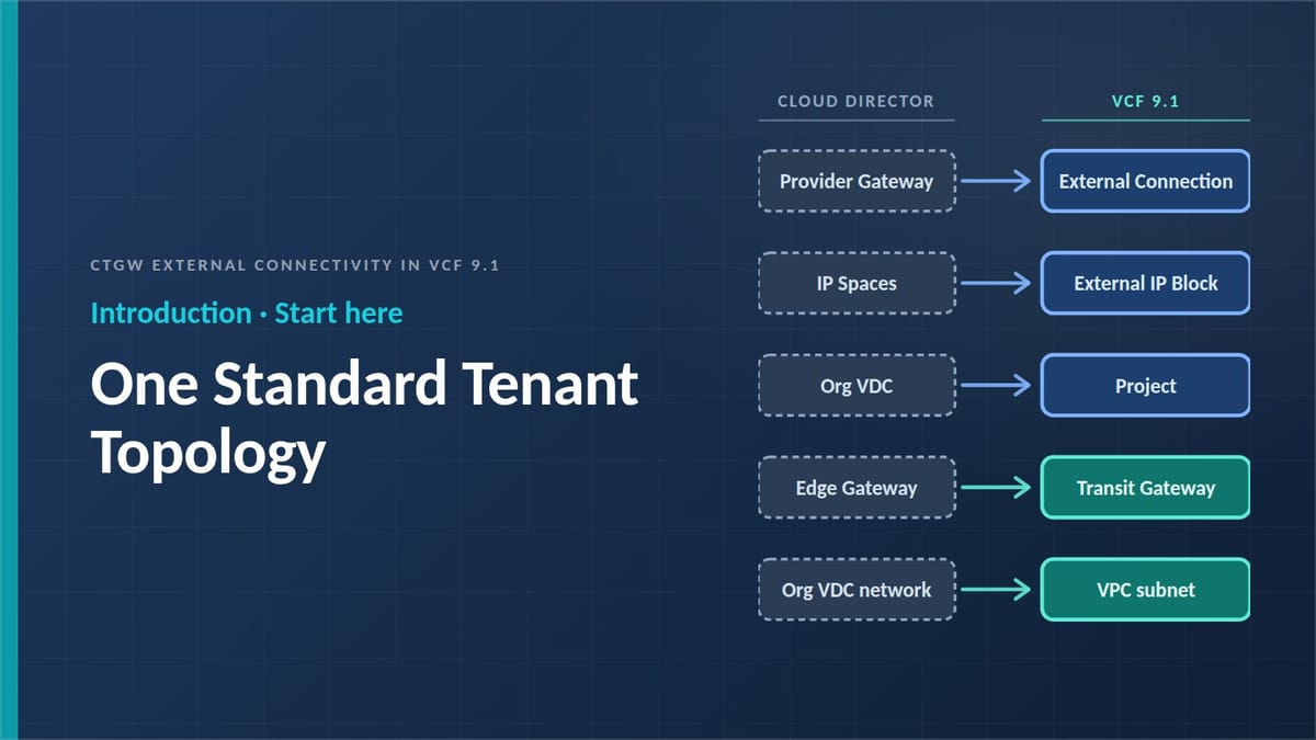
The standard topology has two halves. On VCF 9.1 the provider owns the outside and the tenant owns the inside. The provider creates the routable address ranges (External IP Blocks), the exits toward the world (External Connections, each on a Tier-0 or VRF gateway), and the Project that represents the tenant. Inside that project the tenant runs one Centralized Transit Gateway (CTGW) and its VPCs, where every subnet is Public, Private-VPC or Private-TGW.
With that in place, the tenant's two questions become the provider's two decisions per exit: which exits the CTGW attaches to, and what source address a packet carries when it leaves through each of them.
VCF 9.1 is the release that puts the second decision in the provider's hands. A Transit Gateway can now attach to several External Connections at once, and the provider gets two switches on each one: Provider Outbound SNAT, which translates tenant traffic into a provider-chosen block, and Private-TGW IP block advertisement, which lets a tenant's private range through untranslated.
What the series covers
The stack is VCF 9.1: VCF Automation for organizations, projects and self-service, and NSX for the data plane. Every step is marked with who performs it, provider or tenant, because most behaviours need one action from each.
Nothing here is theoretical. Every scenario in the series was built in full in a lab, tested end to end from the workload to each exit, and validated against the behaviour the platform actually shows, including the intermediate states where a half-finished configuration breaks traffic. The steps, screens and packet walks are written from that build, not from the documentation. One caveat: the lab was built directly in NSX, and VCF Automation was not part of the test. VCF Automation drives the same NSX objects underneath, so the objects, settings and packet behaviour should be the same; only the screens and the order of clicks may differ.
The scope is the Centralized Transit Gateway, the edge-backed model most provider clouds run today. Distributed Transit Gateways, EVPN/VXLAN, the Avi load balancer and vDefend are left out. Addresses and names are illustrative; the rules are the point.
The Internet exit with hidden addresses is the baseline every design includes. Each of the other combinations becomes a complete, lab-validated design, walked packet by packet, including the failure state you get when a setting is missing:
| Design | The tenant | Where |
|---|---|---|
| A | Private-VPC workloads; the enterprise accepts only addresses the provider controls | Part 2 |
| B | Private-TGW workloads; the enterprise routes the tenant's real addresses as they are | Part 3 |
| C | The same tenant, when the enterprise later insists on provider addresses | Part 3 |
| D | One tenant, three exits: enterprise, shared services, Internet | Part 4 |
Part 1 builds the objects in order and states the four rules that decide a packet's source address. Part 5 puts the designs side by side and adds the procedures, checks and ownership needed to run them.
If you are coming from Cloud Director
Broadcom now offers a supported, tool-assisted migration from Cloud Director to VCF Automation 9.1, and Cloud Director 10.6.2 shares its end-of-life date with VCF 9.1. The migration service moves workloads and their networks. What it cannot decide is how each tenant reaches the outside afterwards. That decision is easier to make once, before the move, than tenant by tenant during a migration window.
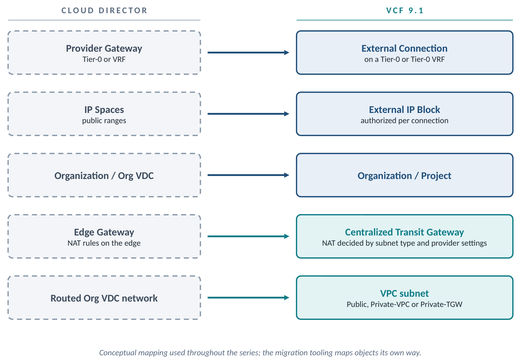
Standardize the backbone and the tenant topology first, and every migrated tenant lands on the same design, the provider keeps the address policy, and the tenant's job is reduced to choosing exits and subnet types.
How to read it
Read in order; each part builds on the last. Parts 2 and 3 share two tenants, Cairo and Alex; Part 4 adds Riyadh. Provider engineers: Part 1, then Part 5. Designing for one tenant: Part 1, then the design that matches. Planning a migration: the whole series once, then pick a design per tenant before you run the assessment tool.
Start with Part 1.
Intro: Tenant Topology for Cloud Providers running VCF9.1 · 1. Architecture and Foundations · 2. Use-Case A Private-VPC Connectivity to External Networks (Translated) · 3. Use-Case B&C Private-TGW Connectivity to External Networks (Routed or Translated) · 4. Use-Case D One Tenant, Three Exits · 5. Operating the Designs